


We manufacture more than a thousand specifications of over ten series of products, including safety valves, power station valves, steam extraction check valves, gate valves, globe valves, check valves, hard-sealed ball valves, all-welded ball valves, ball valves, butterfly valves, and other models and specifications.

DN1400
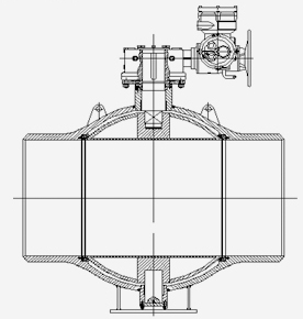
Spherical fixed full-welded ball valve
Product Classification:
Key words:
Overview
This series of fully welded ball valves are widely used in heating pipelines, city gas, municipal construction, and other industrial pipelines. Their main function is to cut off or connect the fluid passage in the pipeline. The closing member rotates 90° around the vertical centerline of the valve body. Clockwise to close, counterclockwise to open.
Structural Features
1. The valve body is welded from two hemispherical forgings, using a single weld seam. The weld seam is located in the middle of the valve body, away from the sealing element.
2. The valve body structure is compact and has greater rigidity, ensuring that the valve remains flexible and free from jamming even under axial pressure, tensile force, and radial bending moment, and that the valve is well-sealed.
3. The valve seat is embedded with soft material polymer sealing rings such as polytetrafluoroethylene suitable for different pressure levels and fluoro-rubber triangular rings, forming a triple seal with a metal hard seal, making the valve seal safer and more reliable.
4. Elastic sealing valve seat, achieving dynamic compensation, solves the problem of excessive friction torque caused by thermal expansion.
5. The valve seat has a self-cleaning function.
6. The ball surface is chemically nickel-plated and then heat-treated to a hardness of HRC>60, improving the ball's anti-bite performance and sealing properties.
Technical Parameters
Design and Manufacturing: GB/T12237、GB/T37827、GB/T12224
Inspection and Testing: GB/T13927、GB/T26480、ISO 5208
Pressure Level: 1.6Mpa~4.0Mpa;
Nominal Diameter: DN500~1400mm;
Applicable Media: Water, gas, oil, etc;
Applicable Temperature: -29℃~200℃.
Product Characteristics
• Low Flow Resistance Coefficient
The pressure loss of the ball valve at the nominal flow rate is the smallest among all valve types, equivalent to the flow resistance coefficient of a pipe of the same length, almost zero; Our company's reduced-diameter ball valves, through fluid analysis and theoretical calculations, have a flow path design that maximizes the valve's flow capacity and reduces the flow resistance caused by the reduced-diameter section.
• Double Seal
The ball valve is not affected by the direction of the fluid medium. Either end of the valve can be used as the upstream end. The fixed ball valve can simultaneously cut off the fluid medium from both upstream and downstream.
• Excellent Sealing Performance
Double valve seat double seal, the valve seat seal is composed of VITONB+non-metallic polymer suitable for different pressure levels+hard seal, ensuring that the ball valve can achieve bubble-level sealing (i.e., zero leakage) under different pressure differences, the sealing is safe and reliable.
• Long Service Life
The sealing surface of the non-metallic material has good lubricity, and the friction and wear with the ball is small. The structure is a multi-stage seal, plus the action of spring pre-tightening force, making the seal safe and reliable, thereby increasing the service life of the ball valve.
Product Installation
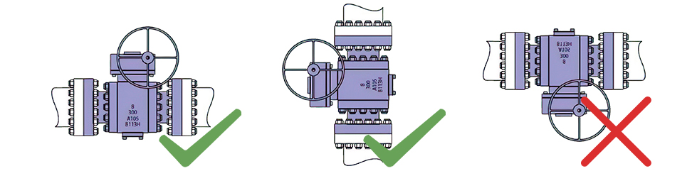
1. The pipelines connected to the valve should be thoroughly cleaned to avoid iron filings, sand, welding slag, and other debris from damaging the valve sealing surface.
2. This series of ball valves can be installed in any position, either end of the valve can be used as the upstream end, both horizontal and vertical installation is possible, but the valve should not be installed upside down to prevent stem corrosion;
3. During installation, the valve should be kept fully open (adjusted at the factory), otherwise it may cause damage to the valve; Warning: Do not leave the valve in a half-open, half-closed state.
4. After the valve center is aligned with the pipe center and pipeline, welding installation can be carried out:
5. Welding connections should be carried out according to welding procedures that have passed welding procedure qualification. During installation welding, prevent welding slag and welding beads from entering the valve cavity and damaging the sealing surface. The valve should be in the fully open position during installation, otherwise it may cause damage to the valve. Warning: For butt-welded ball valves, please do not install while the valve is closed. If the valve must remain closed, apply grease to the exposed ball surface to protect it from damage by splashing welding slag.
6. During preheating, welding, and stress relief, the temperature at any point on the valve body 75mm away from the weld seam must not exceed 200℃, please use a thermometer to check the temperature.
7. During the valve installation process, ensure the cleanliness of the valve body cavity to prevent debris from entering the cavity;
8. After welding of the welded end valves, visual inspection or non-destructive inspection should be carried out to confirm that there are no cracks, weld beads, undercuts, and other harmful defects. Non-destructive testing of the weld seam should be carried out as required:
9. For valves with actuators, the electrical, pneumatic, and hydraulic lines should be connected according to the wiring diagram or piping diagram in the instruction manual. Confirm the correctness of the circuit before connection; The open and close positions of the valve are adjusted at the factory and do not need to be readjusted.
10. The actuator of the buried pipeline valve should not be immersed in water or mud to prevent damage to the actuator; `nbsp_tag
Note: If the valve is inevitably immersed in water or mud for a long time, please inform the manufacturer in advance so that the manufacturer can take countermeasures in advance.
11. When installing large-diameter welded ball valves, the weight of the valve cannot be entirely applied to the pipeline. Fixed piers or supports should be set up for support.
12. Valves with external insulation requirements should have their protective layer constructed before the medium is introduced.
Design Parameters
Design and Manufacture: GB/T12237、GB/T37827、GB/T12224、ASME B16.34
Inspection and Testing: GB/T13927、JB/T9092、I5O 5208
Fire Test: GB/T26479、APl 6FA、API607
Pressure Level: 1.6Mpa~4.0Mpa;
Nominal Diameter Range: DN15~1400mm;
Applicable Medium: Water, gas, oil, etc;
Applicable Temperature: -29℃~200℃。
Main Component Material Details
Component Name | Standard Material | Stainless Steel Material | Low Temperature Material |
Valve Body | A105 | 304 | LF2 |
Valve Cover | A105 | 304 | LF2 |
Ball | F304 | F304 | F304 |
Valve Seat | A105+ENP | 304 | LF2+ENP |
Valve Seat Seal Ring | RPTFE | RPTFE | RPTFE |
Stem | 20CR13 | 304SS | 20CR13 |
Packing Gland | A105 | 304 | LF2 |
Spring | INCONEL X-750 | INCONEL X-750 | INCONEL X-750 |
Trunnion | 20CR13 | 304SS | 20CR13 |
Upper and Lower Diameter | A105 | 304 | A105 |
Sliding Bearing | 304+MOS2+PTFE | 304+MOS2+PTFE | 304+MOS2+PTFE |
O-ring | Fluororubber | Fluororubber | Fluororubber |
Anti-static Device | 304SS | 304SS | 304SS |
Troubleshooting
Malfunction | Cause of Malfunction | Solution |
Operation Jamming | 1. Drive device damage 2. Packing gland installed at an angle 3. Valve seat area blockage 4. Valve stem bending and seizure | 1. Maintain and repair the drive device 2. Loosen the packing gland screws and reinstall the packing gland correctly 3. Turn the handwheel and open and close several times slightly 4. Correct or replace the stem (please contact our company) |
Valve Seat Leakage | 1. Valve not fully closed 2. Drive device limit switch setting incorrect 3. Sealing surface damaged due to scratches | 1. Operate the valve to the fully closed position 2. Adjust the limit switch of the drive device appropriately 3. Please contact our company for repair |
Stem Leakage | 1. Stem seal damaged 2. Stem damaged | 1. Replace the stem packing 2. Repair or replace the stem (please contact our company) |
Online Message
If you are interested in our products, please leave your email and we will contact you as soon as possible. Thank you!
Recommend Products
At present, it can produce more than a dozen series of more than 1,000 specifications of safety valves, power station valves, extraction check valves, gate valves, ball valves, check valves, butterfly valves, drain valves, balance valves, and regulating valves of different types and specifications.


The A42Y-P/R type is suitable for equipment or pipelines with corrosive gaseous media where the operating temperature is ≤200℃, serving as a pressure relief device.
Connecting flanges conform to JB/T 79 standard.


Connecting flanges are in accordance with JB/T79 standard.