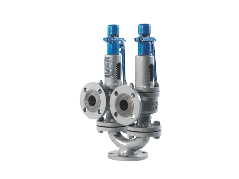
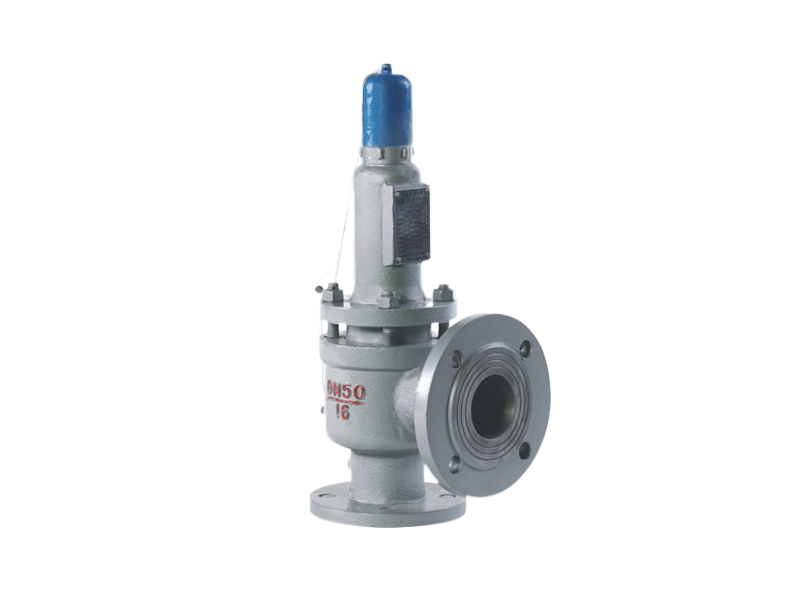
A48sY100~160
Forged high-temperature safety valve
High-temperature safety valves feature a large discharge coefficient, accurate opening pressure, small opening and closing pressure difference, good sealing performance, and convenient adjustment. Material code C- applicable to working temperatures ≤425℃, material code I- applicable to working temperatures ≤510℃, material code V- applicable to working temperatures ≤540℃. They are mainly used as overpressure protection devices on steam pressure vessels, pipelines, and other protected equipment.
Its main features are as follows:
1. A blow-out preventer is installed on the stem, which is fitted and sealed with the lower flange of the heat sink in a concave-convex arrangement. The lower end face of the blow-out preventer has a circular groove, and the lower flange of the heat sink has a retaining ring that can be inserted into the groove. This prevents high-speed hot gas flow from entering the valve cover spring chamber during valve discharge, affecting the spring performance; and prevents dust from entering between the guide tube and the sleeve, reducing the friction during valve opening.
2. A locking sleeve that presses against the upper surface of the valve disc and a limit sleeve located below the heat sink are provided on the valve stem. The locking sleeve is close to the upper end face of the valve disc and is fixed to the valve stem with threads and a cotter pin. It is used to lock the connection between the valve disc and the valve stem; lowering the center of gravity of the stem and increasing its stability. The limit sleeve is fixed to the stem with threads and a cotter pin. It is used to accurately adjust the valve opening height; lowering the center of gravity of the stem and increasing its stability.
3. The safety valve sealing pair uses a valve disc with an elastic self-sealing structure and function. With the reasonable design of the pressure groove and elastic groove, the higher the medium pressure, the more significant the self-sealing effect of the valve disc, and the more reliable the valve seal.
Product Classification:
Key words:
Main Component Materials
| Part Name | Part Material Code | ||
| C | I | V | |
| Valve Body | WCB | ZG14Cr1Mo(WC6)、ZG12Cr2Mo(WC9) | ZG20CrMoV、ZG15Cr1Mo1V |
| Valve Core | 20Cr13 | 06Cr19Ni10(304) | 06Cr19Ni10(304) |
| Valve Cover | WCB | WCB | WCB |
| Sealing Surface Material | Iron-based alloy/Cobalt-based alloy | Cobalt-based alloy | Cobalt-based alloy |
| Spring | 50CrVA | 50CrVA/30W4Cr2VA | 30W4Cr2VA |
Main External Connection Dimensions
| Model | Nominal Diameter DN(mm) | Size(mm) | ||||
| do | L | L1 | DN' | ≈H | ||
| A48sY-100~160 | 20 | 14 | 110 | 105 | 25 | 260 |
| 25 | 14 | 110 | 105 | 32 | 280 | |
| 32 | 18 | 130 | 110 | 40 | 300 | |
| 40 | 20 | 135 | 120 | 50 | 360 | |
| 50 | 25 | 160 | 130 | 65 | 400 | |
| 65 | 30 | 165 | 155 | 80 | 425 | |
| 80 | 40 | 175 | 160 | 100 | 480 | |
| 100 | 50 | 220 | 200 | 125 | 630 | |
| 125 | 65 | 260 | 230 | 150 | 690 | |
| 150 | 96 | 285 | 260 | 200 | 830 | |
| 200 | 110 | 350 | 320 | 250 | 1100 | |
Online Message
If you are interested in our products, please leave your email and we will contact you as soon as possible. Thank you!
Recommend Products
At present, it can produce more than a dozen series of more than 1,000 specifications of safety valves, power station valves, extraction check valves, gate valves, ball valves, check valves, butterfly valves, drain valves, balance valves, and regulating valves of different types and specifications.


